


1500kVA/300kV Series Resonance Withstand Voltage Test Equipment
1500kVA/300kV Series Resonance Withstand Voltage Test Equipment Products Description Overview The HZXB-1500kVA/300kV variable frequency series resonance test system is a complete, field-deployable high-voltage AC withstand voltage (AC hipot) testing solution for cables, generators, GIS...
1500kVA/300kV Series Resonance Withstand Voltage Test Equipment
Product Description
Overview
The HZXB-1500kVA/300kV variable frequency series resonance test system is a complete, field-deployable high-voltage AC withstand voltage (AC hipot) testing solution for cables, generators, GIS switchgear, transformers, and other large capacitive electrical equipment.
The system consists of four integrated subsystems: a 120 kW variable-frequency power supply (HZXB-F-120kW), a 120 kVA multi-tap excitation transformer, two 750 kVA / 150 kV oil-insulated high-voltage reactors, and a 300 kV / 1000 pF capacitive voltage divider. The reactors can be connected in series (300 kV / 5 A) or in parallel (150 kV / 10 A) to match the test object's voltage and capacitance requirements - making the HZXB-1500kVA/300kV a versatile single-system solution for three distinct classes of test objects.
Advantages
1 Resonant Power Amplification - 1,500kVA Output from 120kW Input
The series resonant principle exploits the LC resonance between the high-voltage reactors (L) and the test object's capacitance (C) to achieve a voltage amplification factor equal to the system Quality Factor (Q):
System Q ≥ 30 at f = 45Hz: the 120kVA excitation transformer output is amplified 30× or more across the test object
Practical result: 5kV excitation → 150kV+ test voltage; 8kV excitation → 240kV+ test voltage
Power input: only 120kW (380V three-phase) required at the point of use - compatible with standard substation auxiliary supplies
Weight advantage: the complete system (~2,235 kg total) weighs a fraction of a 1,500kVA test transformer, enabling helicopter or crane-assisted site access to remote substations
2 Dual Reactor Configuration - Flexible Coverage Across Test Objects
| Configuration | Inductance | Rated Voltage | Rated Current | Rated Capacity | Best For |
|---|---|---|---|---|---|
| 2 reactors in parallel | 80H | 150kV | 10A | 1,500kVA | Cables, generators (higher C, lower V) |
| 2 reactors in series | 320H | 300kV | 5A | 1,500kVA | GIS, bushings, transformers (lower C, higher V) |
Each reactor: 750kVA / 150kV / 5A / 160H oil-insulated; Q ≥ 30 at 45Hz; temperature rise ≤ 25K after 90 min at rated load.
3 Variable Frequency Power Supply - 30 to 300Hz Precision Tuning
| Parameter | Specification |
|---|---|
| Frequency range | 30–300Hz (sub-ranges: 30–300Hz, 45–100Hz, 200–300Hz, or custom) |
| Frequency resolution | Selectable: 0.1Hz / 0.2Hz / 0.5Hz / 1.0Hz |
| Frequency stability | 0.1% |
| Output voltage resolution | 0.01kV |
| Output voltage accuracy | ±1.5% |
| Noise level | ≤ 50 dBA |
| Continuous run time | 90 min at rated capacity |
| Automatic voltage regulation | 1.0% stability after lock-on |
The variable frequency approach allows the supply to scan from the set start frequency to end frequency and automatically lock onto the resonant peak - eliminating the need to pre-calculate the exact resonant frequency or manually tune during the test.
4 Three Operating Modes for Maximum Flexibility
| Mode | Description | Best For |
|---|---|---|
| Full Automatic | System auto-scans frequency, locks resonance, ramps voltage in configurable stages, holds timed test, then discharges | Routine acceptance and maintenance testing with single operator |
| Semi-Automatic | Operator initiates each stage (frequency search, voltage ramp, hold); system handles coarse tuning | Diagnostic work where the operator monitors insulation response at each step |
| Manual | Full manual frequency and voltage control via touchscreen or external mouse | R&D testing, impedance characterization, and non-standard test protocols |
5 Intelligent Control System - Large-Screen Touchscreen HMI
The variable-frequency power supply features a large-screen color touchscreen LCD with external mouse interface displaying:
Real-time monitoring:
Resonant voltage (test voltage), test frequency, measured frequency
LV voltage and LV current, withstand time elapsed
Frequency curve and voltage curve for instant visual resonance confirmation
Parameter configuration:
Start/end frequency, start voltage, staged voltage ramp steps and timing
Capacitor-to-inductor-to-frequency conversion calculator
Voltage divider ratio, excitation transformer ratio, protection thresholds
Protection settings (configurable thresholds):
Over-voltage protection, over-current protection, flashover protection
Detuning protection (detects drift from resonant peak), under-voltage protection, zero-position interlock, emergency stop
6 Multi-Layer Safety Protection System
| Protection Function | Trigger Condition | Response |
|---|---|---|
| Over-voltage protection | Test voltage exceeds set threshold | Immediate HV disconnection |
| Over-current protection (LV) | Input current exceeds rated value | Power supply shutdown |
| Flashover protection | Sudden voltage collapse (test object breakdown) | Sub-millisecond disconnection; energy discharged safely |
| Detuning protection | Frequency drift causes resonance loss during test | Alert + auto re-tune or stop |
| Under-voltage protection | Supply voltage dips below safe operating range | Protective shutdown |
| Zero-position interlock | Output voltage not at zero before start | Prevents energization; operator prompted to reset |
| Emergency stop | Operator-activated | Immediate full system shutdown |
All protection events are logged with timestamp and fault code for post-test review.
7 Capacitive Voltage Divider - Precision High-Voltage Measurement
| Parameter | Specification |
|---|---|
| Model | FR-300kV/1000pF |
| Rated voltage | 300kV |
| High-voltage capacitance | 1,000pF |
| Division ratio | 4,000:1 |
| Dielectric loss | tgδ ≤ 0.5% |
| Measurement accuracy | Class 1.5 (RMS value) |
The capacitive divider enables accurate measurement of the actual test voltage on the high-voltage side without direct connection to the HV circuit, meeting IEC 60060 Class 1.5 accuracy requirements for acceptance test reporting.
8 Data Management & Reporting
Data Management Features
Storage: 50 test records (voltage, frequency, timing, protection events) – non-volatile
Export: USB interface for printing/archival
Printer: Thermal or laser (optional, per contract)
Review: On-screen query and re-print capability
Auto Logging: Automatic recording of all voltage steps and timing
FAQ
Q1: Why series resonance over a conventional test transformer? 1/30th power, 2,235kg vs 10,000kg, low flashover.
Q2: How does it find and lock the resonant frequency? Auto scans, detects peak, locks. 10–30s.
Q3: How are the two reactors connected? Parallel 80H for cables/gens; series 320H for GIS.
Q4: What protection is offered against flashover? Sub-ms disconnect. Low fault energy, less damage.
Q5: What are the after-sales service terms? 1yr warranty, lifetime maintenance, 8h response.
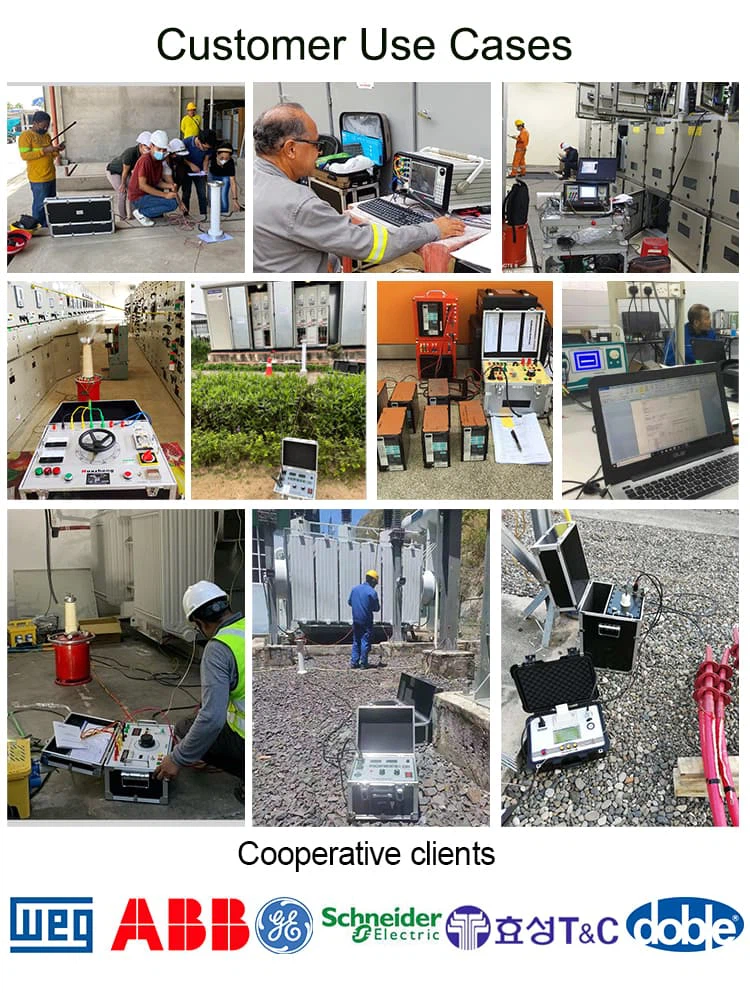
Products Cases
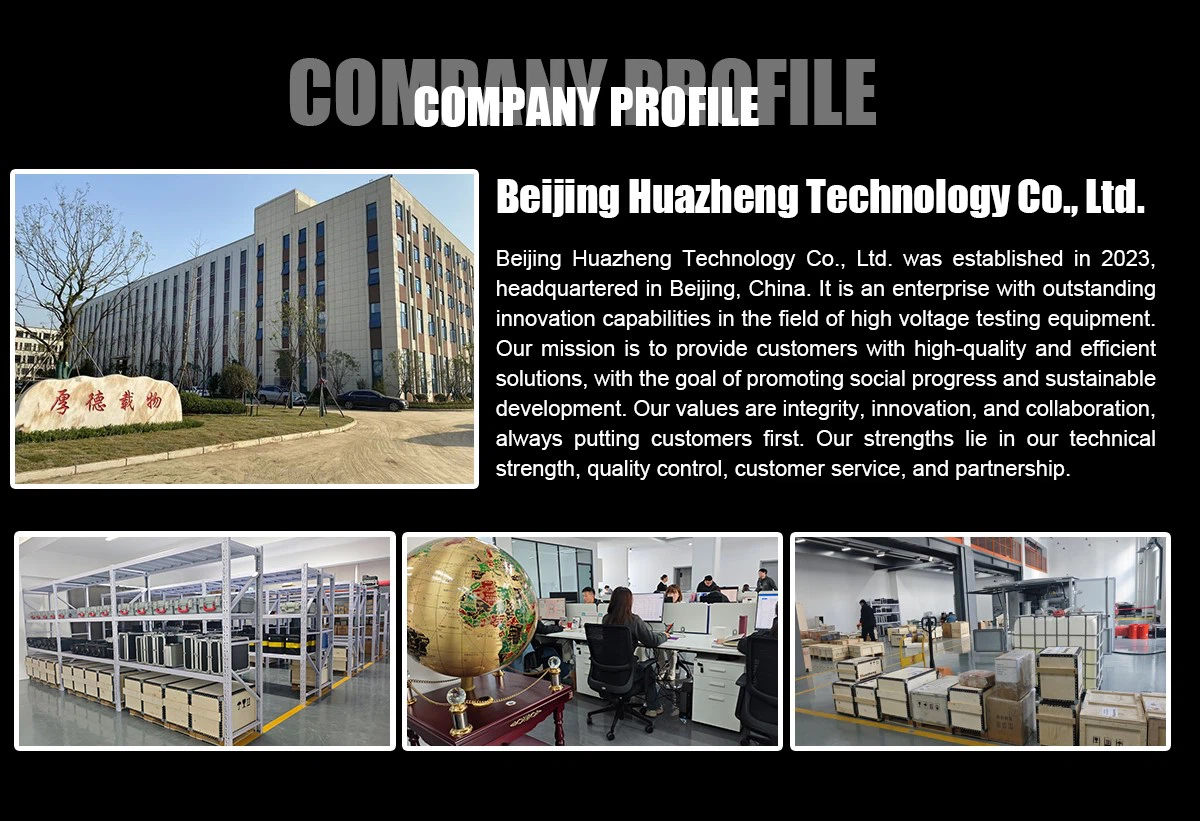
Company Profile
Certification

Related Products

Hot Tags: 1500kva/300kv series resonance withstand voltage test equipment, China 1500kva/300kv series resonance withstand voltage test equipment manufacturers, suppliers, factory, AC Resonance Test System, resonant voltage tester, series resonance voltage withstand test device, variable frequency ac series resonant test system, variable frequency resonant test set, variable frequency series resonance test system


Send Inquiry
