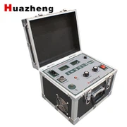
DC Withstand Voltage Tester Function Description
May 02, 2024
1. Control box grounding terminal: The control box grounding terminal is connected to the voltage multiplier grounding terminal and the test sample grounding as one point and then connected to the grounding grid.
2. High-frequency and measurement cable quick connection socket: used to connect the chassis and the voltage multiplier part. When connecting, just turn the cable plug clockwise to the right position. When removing the wire, just turn the cable plug counterclockwise.
3. Power input socket: Connect the randomly configured power cord to the power input socket. (AC 220V±10%, self-contained fuse in the socket.)
4. Overvoltage setting dial switch: used to set the overvoltage protection value. The unit displayed by the dial switch is KV, and the set value is 1.1 times the test voltage.
5. Digital voltmeter: Digital display of DC high-voltage output voltage.
6. Digital ammeter: Digital display of DC high-voltage output current.
7. Power switch: Press forward, the power is turned on, and the green light is on. Otherwise, it is off.
8. Yellow light button: This function is specially used for zinc oxide lightning arrester to quickly measure 0.75UDc1mA. It is effective when the red light is on. When the yellow button is pressed, the yellow light comes on, and the output high voltage drops to 0.75% of the original value, and this state is maintained. Press the green button, the red and yellow lights go out, the high voltage is cut off and exits the 0.75 times state.
9. Red light button: high voltage connection button, high voltage indicator light. When the green light is on, press the red button, the red light comes on and the green light goes out, indicating that the high voltage circuit is connected, and the voltage can be increased at this time. This button is effective only when the voltage adjustment potentiometer is returned to zero. If the red button is pressed, the red light comes on and the green light remains on, but when the button is released, the red light goes out and the green light comes on, indicating that the protection circuit in the machine has worked.
10. Green light button: The green light comes on, indicating that the power supply is connected and the high voltage is disconnected. Press the green button when the red light is on, the red light goes out and the green light comes on, and the high voltage circuit is cut off.
11. Voltage regulator: This potentiometer is a multi-turn potentiometer. Clockwise rotation is for voltage increase, and vice versa for voltage reduction. This potentiometer has the function of controlling electronic zero position protection, so it must be returned to zero before voltage increase.
12. The double-section pressure-multiplying cylinder panel is equipped with a dip switch to select "1" and "2". When a single-section pressure-multiplying cylinder is used, the dip switch is set to "1", and when a double-section pressure-multiplying cylinder is used, the dip switch is set to "2".