

How does a CT PT Analyzer measure the phase error of CT and PT?
Dec 01, 2025
As a reputable CT PT Analyzer supplier, I am often asked about the intricate process of how these devices measure the phase error of Current Transformers (CTs) and Potential Transformers (PTs). Understanding this process is crucial for ensuring the accuracy and reliability of electrical power systems, as phase errors can significantly impact the performance of metering, protection, and control equipment. In this blog post, I will delve into the technical details of how a CT PT Analyzer measures phase error, highlighting the importance of this measurement and the features of our advanced analyzers.
The Significance of Phase Error Measurement
Before we dive into the measurement process, it's essential to understand why phase error measurement is so important. CTs and PTs are critical components in electrical power systems, used to step down high currents and voltages to levels that can be safely measured and monitored by instruments. However, these transformers are not perfect, and they can introduce errors in both magnitude and phase. Phase error, in particular, refers to the difference between the phase angle of the primary and secondary currents or voltages of a transformer.
Inaccurate phase measurement can lead to a variety of issues in power systems. For example, in energy metering applications, phase errors can result in incorrect billing, as the energy consumption is calculated based on the product of voltage, current, and the cosine of the phase angle between them. In protection systems, phase errors can cause misoperation of relays, leading to unnecessary tripping or failure to detect faults. Therefore, accurate measurement of phase error is essential for ensuring the proper functioning of power systems and maintaining the integrity of electrical networks.
How a CT PT Analyzer Measures Phase Error
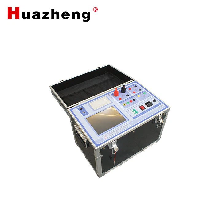
A CT PT Analyzer is a specialized instrument designed to measure the performance characteristics of CTs and PTs, including phase error. The measurement process typically involves the following steps:
1. Connection and Setup
First, the CT PT Analyzer needs to be properly connected to the CT or PT under test. For CTs, the analyzer is connected in series with the secondary winding, while for PTs, it is connected in parallel with the secondary winding. The analyzer is also connected to a reference source, which provides a known and stable voltage or current signal.
Once the connections are made, the analyzer is set up to measure the phase angle between the primary and secondary signals. This may involve configuring the analyzer to the appropriate measurement range, frequency, and other parameters.
2. Signal Acquisition
The CT PT Analyzer then acquires the primary and secondary signals from the CT or PT under test and the reference source. These signals are typically in the form of analog electrical waveforms, which are converted into digital signals by the analyzer's analog-to-digital converters (ADCs).

3. Signal Processing
After the signals are acquired, the CT PT Analyzer processes them to determine the phase angle between the primary and secondary signals. This is typically done using digital signal processing (DSP) techniques, which involve performing mathematical operations on the digital signals to extract the phase information.
One common method for measuring phase angle is the cross-correlation method. This method involves multiplying the primary and secondary signals together and then integrating the result over a specific time period. The phase angle can then be calculated based on the maximum value of the cross-correlation function.
Another method is the phase-locked loop (PLL) method, which uses a feedback control system to lock the analyzer's internal oscillator to the frequency and phase of the input signals. The phase angle can then be determined by comparing the output of the PLL with a reference signal.
4. Error Calculation
Once the phase angle between the primary and secondary signals is determined, the CT PT Analyzer calculates the phase error by comparing the measured phase angle with the ideal phase angle. The ideal phase angle is typically assumed to be zero degrees for a perfect transformer, although in practice, there may be some small deviations due to factors such as core losses and winding resistance.
The phase error is usually expressed in degrees or minutes of arc and can be either positive or negative, depending on whether the secondary signal leads or lags the primary signal.
5. Display and Reporting
Finally, the CT PT Analyzer displays the measured phase error on its screen and may also generate a report that includes the measurement results, as well as other relevant information such as the magnitude error, ratio error, and accuracy class of the CT or PT under test.
Features of Our CT PT Analyzers
At our company, we offer a range of advanced CT PT Analyzers that are designed to provide accurate and reliable phase error measurement. Our analyzers are equipped with state-of-the-art technology and features that make them easy to use and highly efficient.
One of our popular models is the HZCT-100C 0.05% Accuracy Current Transformer CT PT Analyzer. This analyzer offers high accuracy and precision, with a phase error measurement resolution of up to 0.01 degrees. It also features a large color touchscreen display, which makes it easy to view and navigate the measurement results.
Another model is the HZCT-IV Power Frequency CT PT Analyser. This analyzer is specifically designed for power frequency applications and can measure the phase error of CTs and PTs at frequencies ranging from 45 Hz to 65 Hz. It also offers a wide range of measurement functions, including ratio error, magnitude error, and polarity testing.
Our HZCT-100B Variable Frequency Current Transformer Characteristic CT PT Tester is another versatile analyzer that can measure the phase error of CTs and PTs at variable frequencies. This analyzer is ideal for testing transformers in applications where the frequency may vary, such as in renewable energy systems.
Conclusion
In conclusion, accurate measurement of phase error is essential for ensuring the proper functioning of CTs and PTs in electrical power systems. A CT PT Analyzer is a specialized instrument that can measure the phase error of these transformers with high accuracy and precision. Our company offers a range of advanced CT PT Analyzers that are designed to provide reliable and efficient phase error measurement, as well as other important performance characteristics.
If you are in need of a CT PT Analyzer for your power system testing needs, we invite you to contact us for more information. Our team of experts will be happy to assist you in selecting the right analyzer for your specific requirements and to provide you with the support and service you need to ensure the success of your projects.
References
- IEEE Standard C57.13 - Standard Requirements, Terminology, and Test Code for Instrument Transformers
- IEC 60044-1 - Instrument transformers - Part 1: Current transformers
- IEC 60044-2 - Instrument transformers - Part 2: Voltage transformers